
How to test trailer brakes with a multimeter
As a trailer owner, you understand the need for your brakes to work properly.
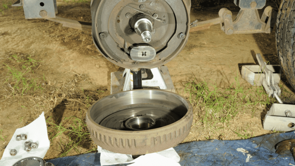
Electric trailer brakes are common with the more contemporary medium-duty trailers, and these come with diagnostic issues of their own.
Your problems go beyond rust or a buildup of deposits around the drum area.
A fault with the electrical system also means your brakes don’t function properly.
However, not everyone knows how to diagnose a problem here.
Our article presents you with all you need to know about testing electric brakes for trailers, including how to simply run diagnostics on electrical components using a multimeter.
Let’s get right in.
How To Test Trailer Brakes With A Multimeter
To test trailer brakes, set your multimeter to Ohms, place the negative probe on one of the brake magnet wires, and place the positive probe on the other magnet wire. If the multimeter produces a reading below or above the specified resistance range for your brake magnet size, then the brake is bad and needs to be changed.
This process is only one method of testing individual brakes and these steps, as well as other methods, will be explained further.
There are three ways of testing your brakes for problems:
- Testing resistance between brake wires
- Testing amperage from the brake magnet
- Testing current from the electric brake controller
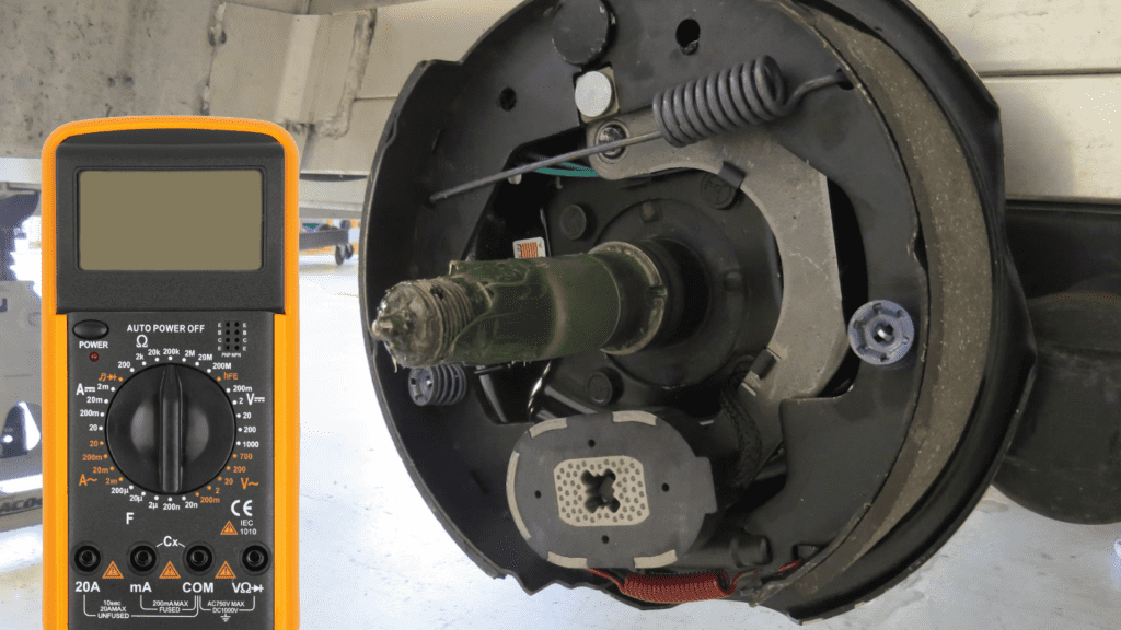
Testing Resistance Between Brake Magnet Wires
- Set Multimeter To The Ohms Setting
To measure resistance, you set your multimeter to Ohms, which is usually represented by the Omega symbol (Ω).
- Position Multimeter Probes
There is no polarity between your brake magnet wires, so you can place your probes anywhere you want.
Place your black probe on any of the brake magnet wires and place the red probe on the other wire. Check for readings on your multimeter.
- Evaluate Results
With this test, there are certain specifications you want to note down.
For a 7-inch brake drum, you expect a reading between 3.0 – 3.2 ohms, and for a 10 – 12-inch brake drum, you expect a reading between 3.8 – 4.0 ohms.
If the reading you get from your multimeter is outside these ranges as they relate to your brake drum size, then the magnet is bad and needs to be replaced.
For instance, the multimeter presenting “O.L” indicates that there’s a short in one of the wires and the magnet probably needs to be changed.
Testing Amperage From Brake Magnet
- Set Multimeter To Measure Ampere
The first step is to put your multimeter on the ammeter setting. Here, you want to measure if there’s any internal exposure or breaks in the wires.
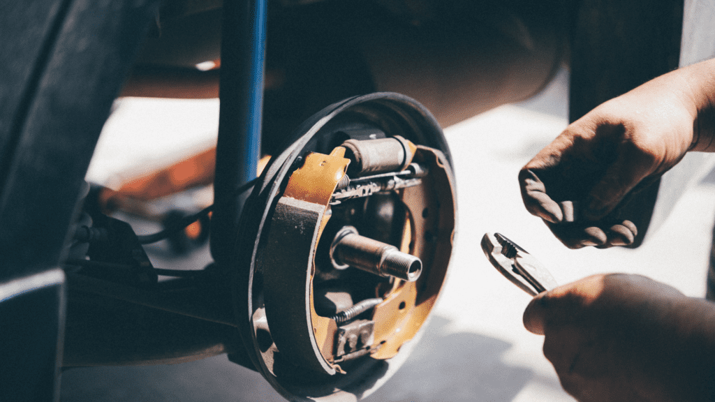
- Position Multimeter Probes
Pay attention to these positions. Place the negative probe on any of your wires and place the positive probe on the positive terminal of your battery.
You then place the brake magnet on the negative battery post.
- Evaluating Results
If you get any ampere reading from the multimeter, then there is an internal short in your brake magnet and it needs to be replaced.
If the magnet is good, you don’t get a reading from your multimeter.
If you have hard time finding right wire check this guide.
Testing Current From The Electric Brake Controller
Electric brakes are managed by an electric brake control panel.
This panel feeds the magnets with electric current when the brake pedal is pressed, and your vehicle stops.
Now, a problem with your brakes arises if this electric brake controller isn’t working properly or current from it isn’t adequately reaching your brake’s electromagnets.
To test this device, there are four methods.
You can use a multimeter to test the trailer brake wiring between your brake controller and the brake magnet.
When generally testing brakes for problems, you want to take note of certain things.
These are the number of brakes you have, your trailer pin plug configuration, and the recommended current the magnet wires are meant to produce.
This recommended current is based on the size of the magnet, and here are the specifications to follow.
For Brake Drum Of 7″ Diameter
- Trailers with 2 brakes: 6.3 – 6.8 Amps
- Trailers with 4 brakes: 12.6 – 13.7 Amps
- Trailers with 6 brakes: 19.0 – 20.6 Amps
For Brake Drum Of 10″ – 12″ Diameter
- Trailers with 2 brakes: 7.5 – 8.2 Amps
- Trailers with 4 brakes: 15.0 – 16.3 Amps
- Trailers with 6 brakes: 22.6 – 24.5 Amps
Now, follow these steps.
- Set Multimeter To Measure Ampere
Set your multimeter dial to the ammeter settings
- Position Multimeter Probes
Connect one probe to the blue wire coming from your connector plug and the other probe to one of your brake magnet wires.
- Take Reading
With your car powered on, activate the brakes through the pedal or electric control panel (you can have a friend do this for you). Here, you want to measure the amount of current coming from the connector to the brake wires.
- Evaluate Results
Using the specifications mentioned above, determine whether you are getting the right amount of current or not.
If the current goes above or below your recommended specification, then the controller or wires may be bad and need to be changed
There are also other tests you could run to diagnose the current coming from your electric brake controller.
In case you see smaller values while measuring the amperage, take a look at this text how milliamps look on a multimeter.
Compass Test
To run this test, simply apply electric current to the brakes through the controller, place the compass near the brakes, and watch if it moves or not.
If the compass doesn’t move, then current isn’t being supplied to the magnets and there could be a problem with your controller or the wires.
Magnetic Field Test
When current is applied to your electronic brakes, a magnetic field is created and, expectedly, metals stick to it.
Look for a metal tool like a wrench or screwdriver and let your friend apply current to the brakes through the controller.
If the metal doesn’t stick, then there could be a problem with the controller or its wires.
Trailer Connector Tester
You can make use of a trailer connector tester to check whether your different connector pins are working.
Of course, in this case, you want to check that the pin for the brake connector is receiving current from the controller.
Simply plug the tester into your connector plug and check whether the appropriate light for brakes comes on.
If it doesn’t, then there is a problem with the controller or its wires and these need to be checked and replaced.
Here is a video on how to operate a trailer connector tester.
Conclusion
There are multiple ways of making a diagnosis on why trailer brakes are not working. We hope we have helped you successfully with this guide.
We highly recommend you to take a look on guide about testing trailer lights.
Frequently Asked Questions
How Many Volts Should Trailer Brakes Have?
Trailer brakes are expected to produce between 6.3 to 20.6 volts for a 7-inch magnet and 7.5 to 25.5 volts for a 10 – 12 inch magnet. These ranges also differ based on the number of brakes you have.
How Do I Check The Continuity Of My Trailer Brakes?
Set your meter to ohms, place one probe on one of your brake magnet wires, and place the other probe on the other wire. An “O.L” reading indicates that there’s a shortage in one of the wires.
How Do You Check Electric Trailer Brake Magnets?
To test a brake magnet, measure the amount of resistance or ampere coming from the brake magnet wires. If you get an ampere reading or O.L resistance reading, there’s a problem with it.
What Would Cause Electric Trailer Brakes Not To Work?
A trailer brake may not work properly if the electrical connections are bad or the brake magnets are weak. Use a meter to test for resistance, voltage, and ampere within the magnet and wires.