
How To Test Resistor With Multimeter
In electronics, the resistor plays a silent yet indispensable role. It’s the unsung hero, ensuring that devices operate seamlessly by managing the flow of electricity. When a resistor fails, however, the harmony is disrupted, leading to electronic device malfunction or complete breakdown.
To mitigate such issues, understanding how to assess the condition of a resistor is essential. With a multimeter in hand and guided expertise, you can quickly and accurately diagnose and resolve issues related to resistors.
In this guide, we will walk you through the systematic process of testing a resistor using a multimeter. Each step is crafted with precision, equipping you with the skills to identify and resolve resistor-related issues confidently.
Tools Required to Test a Resistor
Embarking on the journey of testing a resistor is akin to stepping into a workshop where precision, accuracy, and safety are paramount. Just as a seasoned artist wouldn’t dare touch canvas without their trusted brushes, so should anyone aspiring to test a resistor be equipped with the right tools.
This section unveils the essential instruments that make the process feasible and ensures it’s executed precisely.
- A multimeter
- Electric rubber insulated gloves
- Safety goggles
- Alligator clips
- The circuit or device harboring the resistor
Locating the Resistor
In every electronic troubleshooting journey, identifying the component of interest is the initial yet vital step. Regarding resistors, this component’s modest size belies its significant role in regulating current flow within a circuit.
Whether dealing with a complex circuit board intricately woven into an advanced piece of machinery or a basic electronic device, locating the resistor is pivotal.
Understanding the Circuit
The complexity of the circuit largely influences the ease with which a resistor can be located. In simpler circuits, the task can be straightforward; however, in more complex arrangements, a schematic diagram can be your closest ally.
The schematic diagram visually represents the electronic device’s circuitry, guiding you directly to the resistor’s location.
Decoding the Labels
Resistors are typically labeled with color codes or numerical values, a coding system that indicates their resistance. The color bands or numerical annotations are aesthetic elements and indicative codes that speak the language of resistance value.
Decoding these can provide insights into the resistor’s resistance, tolerance, and reliability.
For those not fluent in this coded language, a resistor color code chart or calculator becomes essential, transforming color bands into numerical values that are easier to understand and work with.
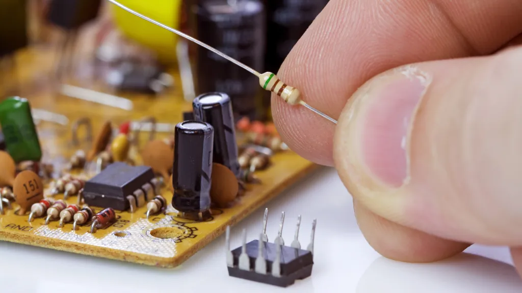
Visual Inspection
A keen eye can often make quick work of locating the resistor. Typically, they are distinguishable components characterized by their cylindrical shape adorned with color bands.
Depending on the type and power rating, resistors can vary in size, from tiny surface-mount versions barely visible to the naked eye to larger, wire-wound types that stand out on a circuit board.
Safety First
Always ensure that the device is powered off before you begin. The safety of the operator – that’s you – is paramount. Ensuring the device is inactive eliminates the risks associated with electric shock or short-circuiting the components.
This small yet critical step lays the foundation for the subsequent stages of testing.
Accessibility
In certain scenarios, especially in compact, modern electronic devices, resistors might be nestled deep within, demanding a partial disassembly of the device to gain access. Here, a set of precision tools and a steady hand are vital.
Always refer to the device’s user manual or seek professional advice if disassembly is required to avoid causing damage.
How To Test Resistor With Multimeter
In the world of electronics, ensuring each component is functioning at its optimal capacity is a necessity. One such vital component, the resistor, requires particular attention.
A step-by-step guide elaborating on how to test a resistor using a multimeter accurately is thus indispensable.
Let’s unravel the steps to achieve this with precision and ease.
1. Gather Necessary Tools
Ensure you have a well-functioning multimeter at your disposal, and if necessary, secure alligator clips to aid in establishing a steadfast connection during the testing process.
2. Safety First
Begin by ensuring the electronic device or circuit is entirely powered off to avoid any risk of electrical shocks. If capacitors are present, ensure they are fully discharged.
3. Identifying the Resistor
Locate the resistor you are looking to test. If embedded within a circuit board, understanding the resistor color codes or numerical annotations can be crucial to identifying the resistance value it’s supposed to offer.
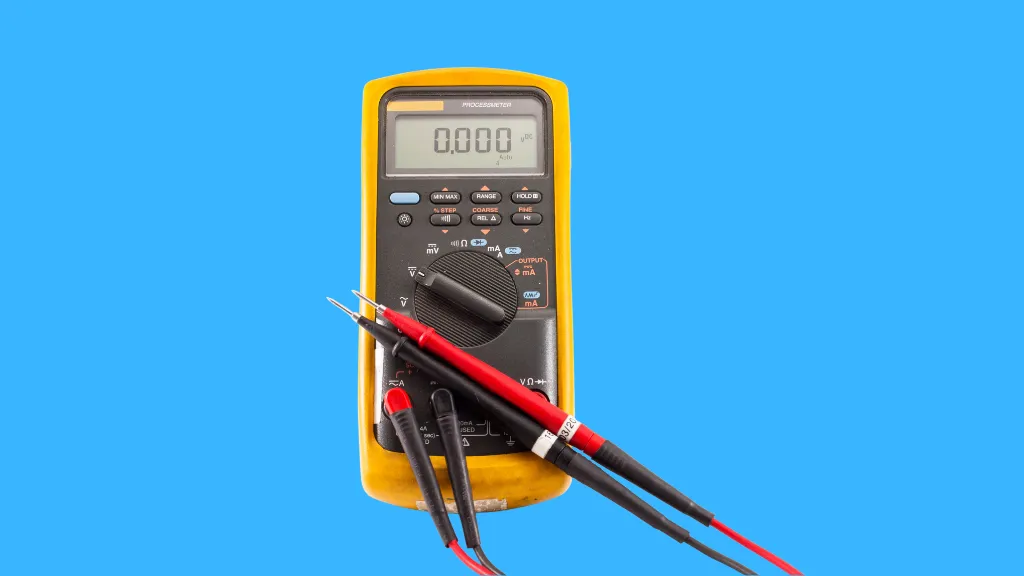
4. Setting Up the Multimeter
Turn the multimeter’s dial to the resistance setting, often indicated by the ohm (Ω) symbol. Ensure the device is calibrated if needed to guarantee accurate readings.
5. Testing the Resistor
Place the probes of the multimeter on the leads of the resistor. The polarity doesn’t matter in this case, as you are measuring resistance, not polarity-sensitive parameters like voltage or current.
6. Recording the Reading
Observe the multimeter’s display. It should indicate the resistance in ohms. Note down this reading; you’ll need it to compare with the expected resistance value indicated by the color codes or printed values.
7. Analysis and Comparison
Contrast the obtained reading with the expected value. A good resistor will exhibit a reading within the specified tolerance range (usually ±5%, ±10%, etc.). If the reading is way off, it indicates a problematic resistor.
8. Physical Inspection
In addition to the multimeter test, visually inspect the resistor for any signs of damage or burning. Physical deformities can sometimes be a clear giveaway of a failed resistor even before you conduct the multimeter test.
9. Conclusive Decision
The resistor is in good shape if the reading aligns with the expected value and there’s no visual damage. If not, replacing the resistor is the next course of action to ensure the optimal performance of your electronic device or circuit.
10. Replacement (if needed)
If the resistor is faulty, ensure you replace it with one of the exact specifications to maintain the circuit’s integrity. Power up the device post-replacement to verify if the issue has been resolved.
11. Documentation
It might be beneficial to document the findings, especially if you are dealing with a complex circuit or device. This record can be instrumental for future reference or maintenance activities.
Each step is pivotal in ensuring the resistor’s functionality is tested comprehensively, mitigating the risk of overlooking potential issues. The focus isn’t just on identifying a faulty resistor.
Still, it extends to understanding the underlying issues and addressing them effectively to ensure the longevity and optimal performance of your electronic devices and circuits.
Safety, accuracy, and thoroughness are the hallmarks of this procedure, ensuring that you are well-equipped to tackle resistor testing with confidence and precision.
Advanced Testing Techniques
For those who have mastered the basics and are looking to expand their expertise, delving into advanced testing techniques can elevate your diagnostic precision, ensuring that every component in your electronic device operates at peak performance.
These methodologies can be especially beneficial for intricate or high-stakes electronics where every ohm of resistance counts.
Safety Measures
In the meticulous journey of testing a resistor with a multimeter, ensuring safety isn’t just a prerequisite—it’s an art. The complexity that marries the intimate dance of currents and resistances is nothing to be taken lightly.
As such, approaching this task requires a set of safety protocols as integral as the multimeter.
Specific steps are paramount before the probes of your trusted multimeter grace the terminals of the resistor. These steps aren’t just procedural but engrained in the ethos of effective and safe electrical diagnosis and repair.
Power Down the Device
The first step is akin to drawing the curtains before the play begins. Power down the device. This isn’t merely flipping a switch or unplugging a cord—it’s the first defense against electrical shock. This clear demarcation line distinguishes safety from potential hazards.
If the resistor is embedded within a larger electronic setup, ensure that the entire system is powered off. It’s a sweeping stroke of precaution that sets the stage, rendering every component, every wire, and every terminal dormant and safe to touch.
Discharge Capacitors
In the silent alleys of circuit boards, capacitors lurk with an eerie ability to retain a charge even when the power is off. These components can be deceptively dangerous.
A part of your safety arsenal is to discharge capacitors to mitigate the risk of electric shock. This isn’t a step to be skipped or glanced over—it’s a ritual to be respected.
Employ Safety Gear
With the device powered down and capacitors discharged, adornment of safety gear follows. This isn’t an act of paranoia but of respect for the silent yet potent energy within the circuits.
Insulating gloves, not just any gloves, should grace your hands. They are barriers and mediators between the skin and the potential residual energy.
Goggles, clear and snug, should nestle on your eyes. They stand as silent sentinels, guarding against the rogue spark, the unpredictable arc that might seek to breach the sanctity of sight.
Environment Check
Now, gaze upon the environment. It’s not just a space; it’s a sanctuary where the dance of diagnosis occurs. Ensure dry, well-lit, and bereft of conductive materials lying astray.
The ambient temperature, too, plays a role. It’s not just the air that kisses the skin—it’s an entity that can influence the readings and sway the dance of electrons within the resistor.
Understanding the Resistor
Finally, understanding the resistor and its domain is crucial before the multimeter is summoned. Is it a lone entity or part of a complex circuit?
Understanding its resistance, nature, and connections is all integral. It’s not just data; it’s the language of the resistor, and understanding it is as pivotal as the readings that the multimeter will soon unveil.
Each step and protocol isn’t just a procedure in this symphony of safety measures. It’s a melody, a harmony that ensures that the dance of testing a resistor isn’t just accurate—it’s safe, respectful of the silent yet potent energy that courses through the veins of every electronic device.
Every measure is a testament to the sacred dance of safety and precision, which begins long before the multimeter hums to life.
Environmental Influences on Resistance
Temperature is one of the crucial environmental factors that can affect the resistance of a component. Each resistor is susceptible to variations in resistance based on its surrounding temperature.
This is quantified by the temperature coefficient of resistance, a parameter that indicates how the resistance of a material changes as temperature varies.
Testing with Temperature Variance:
- Identify the Coefficient: Determine the temperature coefficient of the resistor in question. This information can often be found on the datasheet provided by the manufacturer.
- Measure the Ambient Temperature: Utilize a reliable thermometer to measure the current temperature where the testing is conducted.
- Calculate the Expected Resistance: Adjust the expected resistance value of the resistor based on its temperature coefficient and the ambient temperature.
- Compare with Multimeter Readings: Measure the resistance with your multimeter and compare it to the adjusted expected value to assess if the resistor performs optimally.
Complex Circuit Testing
In more complex circuits, resistors are often found in series and parallel configuration combinations. Testing a resistor in-circuit, especially in these complex scenarios, requires additional steps to isolate the resistor and obtain an accurate reading.
Isolation Technique:
- Power Down and Discharge: Ensure the circuit is powered down and capacitors are fully discharged to avoid erroneous readings or potential safety hazards.
- Identify Adjacent Components: Recognize the components connected in parallel with the resistor, as they can affect the multimeter reading.
- Isolate the Resistor: Temporarily disconnect one end of the resistor from the circuit to isolate it for testing.
- Conduct the Test: With one end of the resistor disconnected, proceed with the standard resistance measurement procedure.
Precision Instruments and Calibration
The accuracy of your multimeter and other testing instruments is pivotal. Precision instruments and regular calibration can vastly improve the reliability of your measurements.
Utilizing Precision Multimeters:
- Choose a Precision Instrument: Invest in a high-precision multimeter, especially for critical or sensitive applications.
- Regular Calibration: Ensure your multimeter is calibrated regularly to maintain its accuracy. Follow the manufacturer’s guidelines on calibration intervals and procedures.
- Verify with Known Values: Test the multimeter on resistors with known values before measuring unknown resistors to confirm their accuracy.
Interpreting the Results
After meticulously following the steps to test the resistor, you find yourself at a crucial juncture where the readings on the multimeter are ready to tell the tale of the resistor’s health. Like the nuanced symphony of an engine’s roar disclosing the secrets of its health and vigor, the numeric dance on the multimeter’s display holds profound insights if read correctly.
First Glance
At this stage, you’ve got your multimeter set, probes firmly touching the terminals of the resistor, and a reading display. It’s a moment of truth, a juncture where numbers translate into insights. Your eyes are fixed on those digits, but the question is, do they spell normalcy or indicate an impending doom?
The Numeric Dance
Essentially, a resistor is characterized by its resistance, denoted in ohms (Ω). For instance, if your resistor is marked as 220Ω, a reading close to this value indicates you are in safe waters.
The song of a healthy resistor is harmonious, where the measured resistance aligns closely with the expected, allowing the electronic device to deliver its optimum performance.
Diving Deeper
But hold on a second. Like the subtle nuances of an intricate melody, there’s more beneath the surface. Resistors come with a tolerance, a small percentage by which the actual resistance can deviate from the marked value and still be considered healthy.
So, if your 220Ω resistor has a tolerance of 5%, readings between 209Ω and 231Ω are your green signal.
The Anomalies
Now, let’s venture into the terrain of anomalies. A reading of ‘OL’ or infinity is the multimeter’s signaling of an open circuit. In the language of electronics, your resistor is akin to a broken bridge, incapable of facilitating the passage of current, warranting an immediate replacement.
On the flip side, a significantly lower reading spells a short circuit. Instead of resisting, the resistor now allows an unrestrained flow of current. It’s like a dam that’s given way, and the consequences can be just as dire for your electronic device.
The Subtleties
Yet, the narrative of numbers is sometimes about extremes. There can be subtle, minor, yet persistent deviations indicative of a resistor heading towards its demise, yet not quite there.
In such instances, experience and intuition join hands with technical knowledge. It’s where the art and science of electronics meld, painting a picture that isn’t stark but holds hues of impending issues.
The Verdict
So, as the digits settle and the readings on the multimeter cease their dance, a verdict is in your hands. It’s a narrative of numbers, a story told in ohms and volts, echoing the resistor’s health, or the lack thereof.
Remember, each resistor is a verse in the symphony of electronics. When in harmony, they elevate a device to its optimal performance.
But even a minor dissonance can cascade into a cacophony of malfunctions. In this delicate balance, the skill of interpreting the multimeter’s readings becomes an art form as intricate, profound, and nuanced as the electronics it seeks to diagnose and understand.
Expert Insights
Each reading, each number, is a piece of a jigsaw puzzle. And like any masterpiece, the beauty lies not just in individual pieces but in how seamlessly they meld to unveil a more extensive, coherent, and harmonious picture.
In this realm, expertise, experience, and education combine, enabling the technician to transcend the apparent, delve into the profound, and unravel the intricate dance of numbers and narratives at any electronic device’s heart.
Frequently Asked Questions
How Accurate Are the Readings from My Multimeter When Testing a Resistor?
Your multimeter should offer readings that are fairly accurate and reliable. However, the precision can vary depending on the quality and calibration of your multimeter. Ensure it’s well-calibrated and in good condition to achieve accurate readings. If in doubt, cross-reference the readings with another trusted multimeter.
Can I Test a Resistor While It’s Still Mounted on the Circuit Board?
Yes, it’s possible to test a resistor in-circuit, but this method can sometimes give inaccurate readings due to the influence of surrounding components. It’s often advised to test the resistor when isolated from the circuit for the most accurate results.
What Does an ‘OL’ Reading Indicate on the Multimeter?
An ‘OL’ (Over Limit) reading typically indicates that the resistor is open or burnt out. It means there’s an infinite resistance, and electrical current can’t pass through the resistor. In such cases, replacing the resistor is usually necessary.
Is There a Specific Multimeter Setting for Testing Different Types of Resistors?
Multimeters often come with multiple settings for measuring resistance. The appropriate setting depends on the expected resistance value of the tested resistor. Consult your multimeter’s manual for detailed instructions on selecting the appropriate settings for different resistors.
How Do I Interpret the Color Codes on Resistors?
Resistor color codes are a standard method of indicating the resistance value of a resistor. Each color corresponds to a specific number, and the sequence of colors on the resistor helps determine its resistance value and tolerance. There are online tools and charts available to help decode these color bands.
What Safety Precautions Should I Take When Testing a Resistor with a Multimeter?
Always ensure the device or circuit is powered off before beginning the test to avoid the risk of electric shock. If you are working on a recently powered device, ensure capacitors are fully discharged. Using insulated gloves and goggles can provide an added layer of safety.
How Do I Know If a Resistor Needs Replacement?
If the resistance reading is significantly off the expected value or the multimeter shows an ‘OL’ reading indicating the resistor is open, it likely needs replacement. Also, visual inspection can be helpful; burnt, discolored, or damaged resistors should be replaced.
Do Environmental Factors Affect the Resistance Readings?
Yes, factors like temperature can influence resistance readings. It’s essential to consider the resistor’s operating environment and temperature coefficient when interpreting results to ensure accuracy.

Author
Alex Klein is an electrical engineer with more than 15 years of expertise. He is the host of the Electro University YouTube channel, which has thousands of subscribers.