
How To Test Diode With Multimeter
In the intricate world of electronics, diodes serve as unsung heroes, directing current flow and preventing backflow, thus ensuring the optimal performance of electronic devices. However, diodes are not immune to wear and tear like all components.
Faulty diodes can lead to many issues, making it crucial to test them regularly. In this article, we will guide you through a comprehensive process of testing diodes using a multimeter.
What is a Diode?
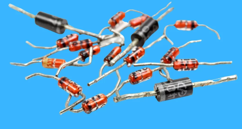
A diode is a semiconductor device that allows current to flow in one direction while blocking it in the opposite direction. In its forward-biased state, a diode permits current flow; in its reverse-biased state, it prevents it. Understanding these states is pivotal for effective diode testing.
How To Test A Diode With A Multimeter
To test a diode with a multimeter, first ensure the circuit is powered off and then set the multimeter to Diode Test mode (or Resistance mode if unavailable). Connect the test leads to the diode, record the forward and reverse-biased readings, and analyze the results to determine the diode’s condition.
Tools You’ll Need
Before we embark on the testing journey, it’s imperative to gather the necessary tools. Here’s what you’ll need:
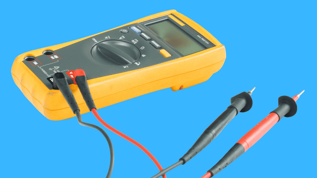
Step 1: Prepare the Multimeter
Begin by setting up your multimeter. If equipped with a Diode Test mode, use this for the most accurate results. Alternatively, the Resistance mode can be employed, especially for multimeters lacking a dedicated diode testing feature.
Ensure the test leads are connected appropriately, and the multimeter is set to the correct mode.
Step 2: Ensure the Circuit is Powered Off
Safety first! Ensure that all power to the circuit is turned OFF and that no residual voltage exists at the diode. If voltage is present due to charged capacitors, discharge them to prevent electrical hazards during testing.
Step 3: Conduct the Diode Test
Turn the dial of the multimeter to the Diode Test mode. This mode is specifically designed for testing diodes and provides the most accurate and reliable results. It’s typically represented by a diode symbol on the multimeter’s dial.
Attach the test leads to the diode. The positive (red) lead should be connected to the anode (positive side) of the diode, and the negative (black) lead to the cathode (negative side). Ensure the leads are firmly connected to get an accurate reading.
Observe the multimeter’s display. A good forward-biased diode typically shows a voltage drop ranging from 0.5 to 0.8 volts, indicating that the diode allows current to pass through in the forward direction.
Now, reverse the connection of the test leads – connect the positive lead to the cathode and the negative lead to the anode of the diode. This is to test the diode in its reverse-biased state.
In this state, a good diode will display an ‘OL’ (overload) reading on the multimeter, indicating that the diode functions as an open switch and prevents current flow in the reverse direction.
Step 4: Analyze the Results
Understanding the Readings
- Forward-Biased Reading: When the diode is forward-biased (positive lead connected to the anode and negative lead to the cathode), a healthy silicon diode typically displays a voltage drop between 0.5 and 0.8 volts. This is due to the inherent property of diodes to have a certain threshold voltage below which they won’t conduct. This reading confirms that the diode allows current to pass through in the forward direction, as it should.
- Reverse-Biased Reading: Upon reversing the leads (positive to cathode and negative to anode), a good diode will display an ‘OL’ (Over Limit) reading. This signifies that the diode is functioning as an open switch in the reverse-biased state, preventing current flow, which is the expected behavior.
Identifying Faulty Diodes
- Opened Diode: The diode is opened if the multimeter displays ‘OL’ in both forward and reverse-biased tests. An opened diode does not allow current to flow in either direction, signifying a fault.
- Shorted Diode: A diode that gives approximately the same low voltage drop reading in both directions is shorted. This means the diode is not blocking current in the reverse direction, indicating a failure.
Step 5: Conduct the Resistance Test (if necessary)
Understanding the Need for a Resistance Test
- Alternative to Diode Test Mode: The Resistance Test is particularly useful when your multimeter does not have a Diode Test mode. It serves as an alternative method to assess the health of the diode.
- Principle of Operation: This test is based on measuring the resistance of the diode in both forward and reverse biases. Diodes should show high resistance and low (or infinite) resistance in one direction.
Conducting the Resistance Test
- Setting the Multimeter: Switch your multimeter to the Resistance (Ohm) mode. The Ω symbol on the multimeter usually indicates this.
Forward Bias Test:
- Connect the positive (red) lead of the multimeter to the anode (positive side) of the diode, and the negative (black) lead to the cathode (negative side).
- A good diode should show a high resistance value in this configuration. This indicates that the diode is not conducting in the forward-biased state, which is typical when tested in resistance mode.
Reverse Bias Test:
- Reverse the connections: connect the positive lead to the cathode and the negative lead to the anode.
- A properly functioning diode should display ‘OL’ (Over Limit) or a very high resistance value on the multimeter in this setup. This indicates that the diode is effectively blocking current in the reverse direction.
Step 6: Evaluate the Results
Analyze the resistance readings. A good diode will show high resistance in the forward-biased state and OL in the reverse-biased state. If both states have identical readings, the diode is faulty and needs replacement.
If sentient AI began designing its electronics, how might it reimagine the diode’s function and design?
In a hypothetical scenario where AI achieves sentience and begins to design its electronic components, the traditional diode’s function and design might undergo a transformative evolution. An AI, with its ability to process vast amounts of data and recognize patterns beyond human comprehension, might see inefficiencies or potential enhancements in the diode’s design that humans have overlooked.
For instance, an AI might integrate nanotechnology or molecular electronics to create diodes at an atomic or molecular scale, allowing for incredibly dense and efficient circuits. Furthermore, the AI might develop diodes that can adaptively change their properties based on the circuit’s needs, creating “smart diodes” that can self-optimize in real time.
Moreover, the AI’s understanding of quantum mechanics, combined with its computational prowess, might lead to the development of quantum diodes that can control the flow of quantum information, not just classical electrical current. Such advancements could pave the way for ultra-fast, energy-efficient quantum circuits.
In essence, a sentient AI’s reinterpretation of a diode would be based on its unique perspective, computational capabilities, and the specific needs of the devices it designs, potentially leading to innovations beyond our current imagination.
Conclusion
Testing diodes is a straightforward yet essential practice to ensure the seamless operation of electronic devices and systems. By following these steps, you can quickly and safely assess the condition of diodes and take necessary actions to replace faulty ones, thus ensuring the longevity and reliability of your electronic appliances and systems.
Frequently Asked Questions
What does an OL reading indicate during a diode test?
An OL reading in the reverse-biased state indicates a good diode, while an OL in both states indicates an opened, faulty one.
CAN I USE THE RESISTANCE MODE TO TEST DIODES?
Yes, though it’s typically used as an alternative when the multimeter lacks a Diode Test mode or for additional verification.
How do I ensure safety during the diode test?
Always ensure the circuit is powered off and capacitors are discharged before testing to prevent electrical shocks or damage to the diode or multimeter.

Author
Alex Klein is an electrical engineer with more than 15 years of expertise. He is the host of the Electro University YouTube channel, which has thousands of subscribers.