
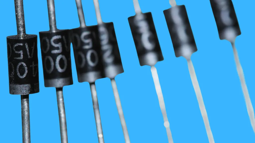
How to Tell if a Diode is Bad
Diodes are crucial components in electronic circuits, often responsible for directing current flow. However, like any component, they can fail. Identifying a bad diode is essential for troubleshooting and maintaining electronic devices.
This article will guide you through testing a diode using a multimeter, a versatile tool in electronics.
Understanding Diodes
Basic Function of a Diode
A diode is a semiconductor device acting as a one-way current switch. Its primary function is to allow electric current to flow in one direction while blocking it in the opposite direction.
This unique characteristic is due to the way diodes are constructed.
Construction and Operation
A diode is made from a semiconductor material, typically silicon, doped with impurities to create two distinct regions: the P-type and the N-type. The P-type region contains positive charge carriers (holes), while the N-type region contains negative carriers (electrons).
At the junction of these two regions, a barrier is formed that only allows electrons to move in one direction.
The junction barrier is thinner when a diode is in a forward-bias condition, with the positive voltage connected to its P-type side and the negative to its N-type side. This reduction in the barrier allows electrical current to pass through the diode.
On the other hand, in a reverse-bias scenario where the P-type side is connected to the negative voltage and the N-type side to the positive, the junction barrier increases in width, effectively impeding the flow of current.
Signs of a Faulty Diode
Identifying a faulty diode is crucial for ensuring the proper functioning of an electronic circuit. While some signs of a bad diode are visible, others require testing to confirm.
Here are common indicators that a diode may be failing or has already failed:
Visible Damage
Physical inspection can sometimes reveal problems:
- Burn Marks or Discoloration: Overheating can cause the diode to burn or discolor.
- Cracks or Physical Deformation: Physical damage to the diode, possibly due to impact or overheating.
- Corrosion or Rust: This can indicate exposure to moisture or corrosive environments, compromising the diode’s integrity.
Unusual Sounds or Smells
Electronic components shouldn’t emit any noise or odor during normal operation:
- Buzzing or Hissing Sounds: While hard to detect, these can indicate internal damage or malfunction.
- Burning Smell: A telltale sign of an overheated or damaged diode.
Malfunctioning of the Electronic Device
The device the diode is a part of may exhibit abnormal behavior:
- Power Supply Issues: If the diode is part of a power supply circuit, the device might not turn on or experience intermittent power failures.
- Irregular Output in Rectifier Circuits: Inconsistent or fluctuating DC output in a circuit that uses diodes for rectification can signify diode failure.
- Signal Distortion: In applications like radio receivers, a bad diode can lead to poor demodulation of signals, resulting in distorted audio or data output.
How to Tell if a Diode is Bad
Tools Needed
Setting Up the Multimeter
Properly setting up your multimeter is critical in accurately testing a diode. Here’s a detailed guide to ensure you’re ready for the test:
Selecting the Correct Mode
- Identify the Diode Test Setting: Most digital multimeters have a specific setting for testing diodes, often denoted by a diode symbol (a triangle pointing to a line). This setting sends a small current through the diode to measure the voltage drop across it.
- Switch to Diode Test Mode: Turn the dial or select the button on your multimeter to set it to diode test mode. This mode differs from the standard resistance (ohms) or continuity settings.
Check Multimeter Functionality
- Battery Check: Ensure that the multimeter’s battery is in good condition. A weak battery can lead to inaccurate readings. Most digital multimeters display a low battery indicator.
- Calibration Check: If your multimeter has been calibrated, ensure it’s within its calibration period for accurate measurements. Calibration is usually not an immediate concern if it’s a newly purchased or rarely used multimeter.
- Test on a Known Diode: If available, test the multimeter on a known good diode to confirm it’s working correctly. The reading should align with the expected forward voltage drop for that type of diode (typically 0.5 to 0.8 volts for silicon diodes).
Prepare Test Leads
- Connect the Leads: Insert the black test lead into the COM (common) jack and the red test lead into the VΩmA jack. Ensure they are firmly plugged in.
- Inspect the Leads: Check the condition of the test leads. Look for any damage, exposed wires, or loose connections. Damaged leads can lead to inaccurate readings or safety hazards.
Locating the Diode in the Circuit
- Identify the Diode: First, locate the diode within the circuit. Diodes are typically marked with a symbol (an arrow pointing towards a vertical line) and are polarized components, meaning they have a specific flow direction. Look for diode or circuit board markings, such as a line or band, indicating the cathode (negative side).
- Accessing the Diode: You should remove it from the board for accurate testing if it is in a circuit. This is especially true if the circuit has parallel pathways that could affect the test results. However, in many cases, in-circuit testing can be sufficient for a preliminary check.
Performing the Diode Test
- Attach the Probes of the Multimeter: Ensure your multimeter is switched to diode test mode. Affix the red probe to the anode, which is the positive side of the diode, and the black probe to the cathode, the diode’s negative side. This setup is used for conducting the forward bias test.
- Forward Bias Test: In this configuration, a good silicon diode typically shows a voltage drop between 0.5 and 0.8 volts, indicating that current is flowing through the diode. If the multimeter displays a reading in this range, the diode is conducting in the forward direction as it should.
- Reverse Bias Test: Next, reverse the connections—black probe to the anode and red probe to the cathode. This tests the diode in reverse bias. A good diode will show ‘OL’ (overload) or a very high resistance, indicating that it blocks current in the reverse direction.
Understanding the Results
Interpreting the results correctly is crucial when testing a diode with a multimeter. The readings can help you determine whether the diode is functioning properly or has failed.
Interpreting Forward Bias Test Results
- Normal Reading: In forward bias (positive to the anode, negative to the cathode), a healthy silicon diode typically shows a voltage drop between 0.5 and 0.8 volts. This indicates that the diode allows current to pass in the correct direction.
- High Reading: If the voltage drop is significantly higher than 0.8 volts or if the multimeter shows an ‘OL’ (overload) reading, it suggests that the diode is not conducting properly in the forward direction, indicating an open diode.
- Low or Zero Reading: A very low or zero reading in forward bias might indicate that the diode is shorted, allowing too much current to pass through without the expected resistance.
Interpreting Reverse Bias Test Results
- Normal Reading: In reverse bias (positive to the cathode, negative to the anode), a good diode should show ‘OL’ or a very high resistance, indicating that it effectively blocks current in the reverse direction.
- Low Reading: If the multimeter shows a low resistance or a measurable voltage drop in reverse bias, it suggests that the diode is shorted and allows current to pass through in the wrong direction.
Diode Condition Assessment
- Good Diode: Consistent with the expected forward and reverse bias readings, a good diode conducts in one direction and blocks in the other.
- Faulty Diode: Deviations from the expected readings indicate a faulty diode. A diode that conducts or shows low resistance in both directions is shorted, while one that blocks or shows high resistance in both directions is open.
- Variable or Inconsistent Readings: If the diode shows fluctuating readings, it might be unstable or damaged. Environmental factors, poor connections, or internal diode damage could cause inconsistencies.
Can a Multimeter Be Used to Test All Types of Diodes, Including LEDs, and How Does the Testing Process Differ for Different Types of Diodes?
Yes, a multimeter can be used to test various types of diodes, including standard silicon diodes, Schottky diodes, Zener diodes, and Light Emitting Diodes (LEDs). However, the testing process and the interpretation of results can vary slightly depending on the type of diode.
- Standard Silicon Diodes: These are tested using the diode test mode on the multimeter, which measures the forward voltage drop (typically 0.5 to 0.8 volts for silicon diodes) and checks for blocking in reverse bias.
- Schottky Diodes: These are known for their low forward voltage drop, often around 0.2 to 0.3 volts. When testing Schottky diodes, expect a lower forward voltage reading than standard silicon diodes.
- Zener Diodes: Testing Zener diodes can be more complex. While the forward bias test is similar to standard diodes, testing in reverse bias requires a specific setup to measure the Zener voltage. This often involves applying a reverse voltage and a series resistor, which may not be feasible with just a multimeter in a simple diode test mode.
- Light Emitting Diodes (LEDs): When testing LEDs with a multimeter in diode mode, you can see the LED light up if it’s working. The forward voltage drop for LEDs varies depending on the color and type but is typically higher than standard diodes (ranging from about 1.2 volts for infrared LEDs to over 3 volts for blue and white LEDs). The LED is good if the LED lights up and the multimeter shows a forward voltage within the expected range. However, the LED may be damaged if it doesn’t light up or the multimeter shows ‘OL’ in forward bias.
Conclusion
Testing diodes is a vital skill in electronics. By following the steps outlined, you can efficiently determine the health of a diode using a multimeter.
Regular testing and maintenance are key to the longevity of electronic devices. If you’re ever in doubt, don’t hesitate to consult a professional.

Author
Alex Klein is an electrical engineer with more than 15 years of expertise. He is the host of the Electro University YouTube channel, which has thousands of subscribers.