
Multimeter Symbols
Are you new to testing electrical equipment with a multimeter, or do the icons and symbols on the multimeter seem confusing to you? If your answer to these is yes, then we are glad you came here before proceeding further.
Using a multimeter without knowing what its symbols mean doesn’t just make your electrical diagnostic processes almost impossible. It puts the multimeter itself and even you at risk of harm.
Our guide tells you the meaning of every multimeter symbol you may come across over time and without much ado, let’s get into it.
Multimeter Symbols
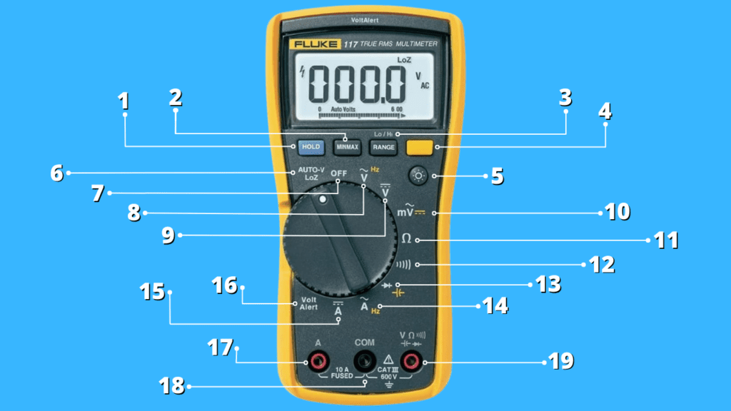
Number 1: Hold Button

The hold button is simply used to freeze a multimeter reading on the screen. When pressed, your measurement remains on the multimeter screen after you have taken your probes off the device you are testing.
It is great to use if you work with very precise measurements that are hard to memorize or you aren’t looking at the multimeter when measuring.
Number 2: MIN MAX Button

Common with higher-end multimeters, the Min Max function helps you to register minimum and maximum values within a range to monitor reading fluctuations or anomalies.
You preset a maximum and minimum limit for the multimeter reading, take a steady measurement, hit the MIN MAX button, and receive beeps when any of the limits are crossed.
Number 3: Range (Lo/Hi Button)

The Range button is used to switch between different ranges for measurements. Note that multimeters measure at different levels, for example, there is a 200V limit and a 600V limit for AC voltage. The Range button is used to switch between these different range limits for a more accurate and precise reading.
Nonetheless, the more modern meters come with an auto-ranging feature that simply boycotts the need for this button. The multimeter handles the ranging by itself.
Number 4: Function Button

The function button is used to activate the secondary options on multimeters.
These options are usually placed beside the primary functions, represented with a different color imprint (like yellow or red), and are typically related to temperature and capacitance measurements.
Number 5: Brightness Button

The brightness button lets you turn off or turn on the backlight of your display. You set the brightness level of your screen for easier use whether indoors or outdoors.
Number 6: Auto-V LoZ

The Auto-V setting allows multimeters to automatically detect the type of voltage you are measuring (either AC or DC voltage) and get in the appropriate measurement mode and range.
Loz serves as “Low Impendence” and defines the range of resistance (4 – 16 Ohms) needed for the Auto-V function to work.
Number 7: Off

This is the switch to simply turn on or turn off the multimeter.
Number 8: AC Voltage and Shift: HerTz Symbols

“V~” is a dedicated AC voltage setting that is typically used to measure voltages between 100 and 240 AC volts around homes and offices. This usually comes with two different ranges; 200V~ and 600V~, and may also be labeled “VAC”.
The additional “Hz” imprint in yellow represents the Shift: Hertz secondary function used to measure the AC voltage frequency of your circuit or equipment.
Number 9: DC Voltage Setting

“V—” is a setting used to measure DC voltage typically from a circuit or devices that make use of batteries.
It may also be labeled “VDC” and come with six different ranges; 2m, 200m, 2V, 20V, 200V, and 600V in some multimeters.
Number 10: AC and DC Millivolts Symbols

“mV~” is used to measure millivolts, which are much smaller ranges of AC voltage. If the device or circuit you test uses extremely low AC voltage, then this setting helps the multimeter recognize this and give you a more accurate reading.
The yellow icon serves as a secondary function used to switch to the DC millivolts setting. The separate AC and DC millivolts symbols are usually present when all the ranges are not listed at the regular AC and DC voltage sections.
Number 11: Resistance Setting

The horseshoe or omega symbol on the multimeter represents Ohms, which is the measurement unit for resistance. It helps you test the continuity and specific resistance between two points in a circuit.
If there is no continuity, the multimeter presents you with “O.L” when you use the resistance setting.
Number 12: Continuity Mode

Sometimes combined with the resistance symbol, the soundwave icon on multimeters represents the continuity mode, a simple setting used to test the electrical path between two points in a circuit. If there is continuity, the multimeter produces a beep and if there is none, the meter remains silent.
Placing your multimeter probes together makes the meter emit a beep and helps you test if the setting is working or not.
Number 13: Diode and Capacitance Test Symbols

The right-pointing arrow represents the diode test setting. Although the resistance setting may be used for this, the diode test setting is the most accurate mode for diagnosing if a diode is good or faulty.
The yellow imprint beside it that looks like two TT placed side by side is a secondary function used to measure capacitance. Make sure the capacitor you wish to test doesn’t have any current running through it before proceeding.
Number 14: Alternating Current

The “A~” on the multimeter icon represents the alternating current setting, which is used to measure the specific amount of alternating current drawn by an electrical device or equipment.
For this, the multimeter is usually used with a clamp attachment positioned around a wire. The “Hz” imprint is a secondary function to measure the alternating current frequency.
Number 15: Direct Current

The “A—” setting is used to measure the specific amount of direct current used by an electrical device or equipment. Just like the alternating current setting, the multimeter is additionally used with a clamp attachment positioned around a wire.
If you’ve never measured DC current, we recommend you check out our guide on how to measure DC Amps.
Number 16: Volt Alert

Voltage alert, (or sometimes “V-Chek” as seen in some Fluke multimeters) is a setting usually found on higher-end multimeters used to detect the presence of voltage. You may use it to also measure voltage and continuity at the same time.
Number 17: Current Jack Port

The jack port labeled “A” and usually lined with red is used only when you want to measure current values expected to be higher than 200 milliamps. You always plug your red positive multimeter probe into this port to avoid any confusion when following our multimeter guides.
With the port also labeled “10A Fused” sometimes, you also want to always use this port when you are not sure of the amount of current running through the circuit. You do this to avoid blowing the internal multimeter fuse.
Number 18: Common Jack Port

The “COM” jack is the port where you always plug the black multimeter probe into. “COM” represents Common, and the port is usually lined with black and used for all multimeter measurements.
Number 19: mAVΩ Jack Port

The main jack port of the multimeter is used for all measurements when you work with current below 200 milliamps. This port is typically labeled with a variety of symbols since it is used for all the multimeter measurements, whether milliamps, AC voltage, DC voltage, resistance, or a test on a diode, among others.
You always plug the red multimeter probe into the port and, as said earlier, you only opt for the current jack port when measuring current above 200 mA.
Having knowledge of these multimeter symbols helps you run accurate and comprehensive tests on your circuits and devices. However, you need to take some extra safety measures to protect both you and the meter from harm.
Multimeter Safety Measures
Ensure that your multimeter probes are not damaged in any form to avoid short circuits or current leakage, as these could affect the accuracy of your reading.
You also test out all the functions on the multimeter and additionally make sure that the lights and sounds are all working perfectly.
Check to see if its internal fuse isn’t blown, always plug the probes deep into their appropriate ports, and, lastly, never allow the two multimeter probes to make contact during an electrical test.
Video Guide
You can also watch our video guide on this topic:
Conclusion
Making use of a multimeter is very easy and memorizing what each of its symbols represents is way simpler than you may expect. Apart from just knowing what the symbols mean, however, you should understand just when to use each multimeter setting to get the most precise results.
FAQs
What Is The Symbol For Ac Voltage?
AC Voltage is usually represented by “V” with a wavy dash on top of it, “V~”, or “VAC”. Millivolts, on the other hand, are represented by an “m” placed before the corresponding symbol (e.g, “mV~”).
What Is The Symbol For Ohms On A Meter?
Ohms, which is used to measure resistance, is represented by the horseshoe sign or Omega symbol (Ω). You may see a sound wave symbol placed beside it which is used for the continuity mode.

Author
Alex Klein is an electrical engineer with more than 15 years of expertise. He is the host of the Electro University YouTube channel, which has thousands of subscribers.