
How To Test A Relay With A Multimeter
Did your car engine stall while in use? Are your dashboard lights flicking erratically or does your ignition system seem completely dead? If your answer is yes, then your relay switch may be faulty.
However, how can you be so sure of this?
Testing your relay with a multimeter is one of the most accurate diagnoses you may make, and we will tell you all you need to know, including what a relay is and what you need to run tests.
Let’s get right in.
What Is A Relay
A relay is an electrically-operated switch, which is a contrast to mechanically-operated switches. The relay is a switch within your vehicle that makes use of electrical signals to either close or open its internal circuit for current to pass through. This switch system replaces the regular mechanical levers.
How does a relay switch work
Well, most relays are electromechanical switches that make use of an armature, coil, a moving contact, and magnetism to perform their function. They typically have four terminals with externally protruding pins; two normally closed (NC) control terminals and two normally open (NO) load contacts.

Power is supplied to the coil through the NC control terminals causing the coil to generate an electromagnetic field and pull on the moving contact within the relay. The contact then touches on another contact, which closes the path between the NO terminals, allowing current to pass through.
Function Of A Relay In A Vehicle
When used in cars, relays serve as intermediaries between low-current and high-current components that have to work together. They are used to protect the low-current components from damage caused by an excessively high voltage or power supply.
For example, the ECU is a low-current component that controls the voltage supply to your fuel pump. As we can’t pass high-voltage current through the ECU because of the potential damage, the relay is then used as an intermediary switch.
The ECU supplies voltage to the relay switch instead, which energizes its coil and ultimately closes the contact and path between the NO terminals. This then allows the necessary amount of power to flow to the fuel pump.
Due to the high voltage relays deal with, it isn’t surprising to see why one used in your car may develop a fault. So, rather than hastily testing a fuel pump, you then test the electrical relay first.
Tools Required To Test A Relay
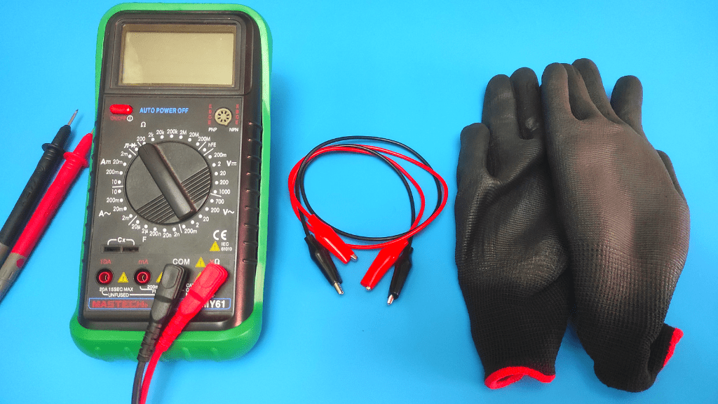
To test a relay, you will need
- Multimeter
- Protective equipment
- 12-voltage battery
- Jumper cables
How To Test A Relay With A Multimeter
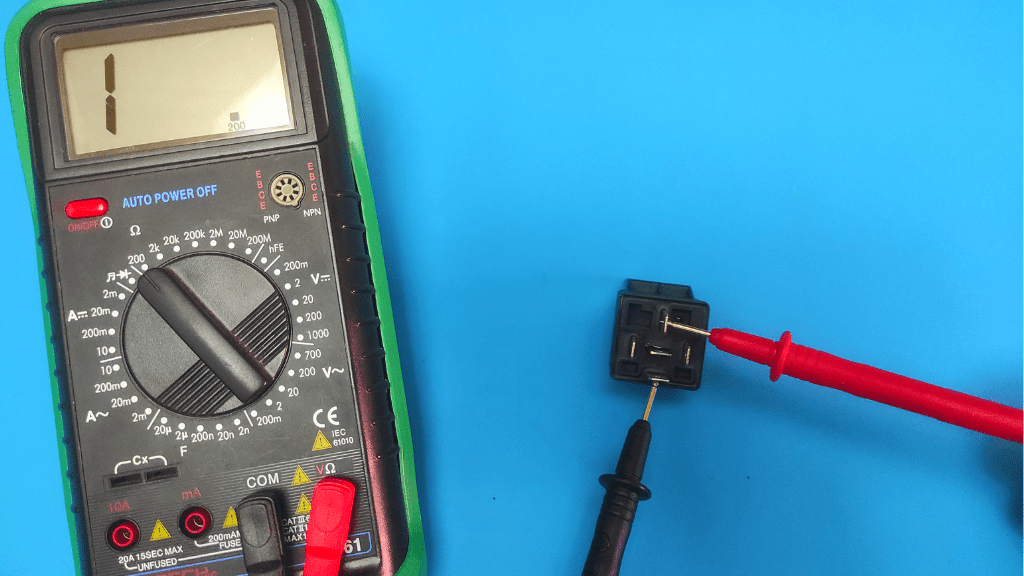
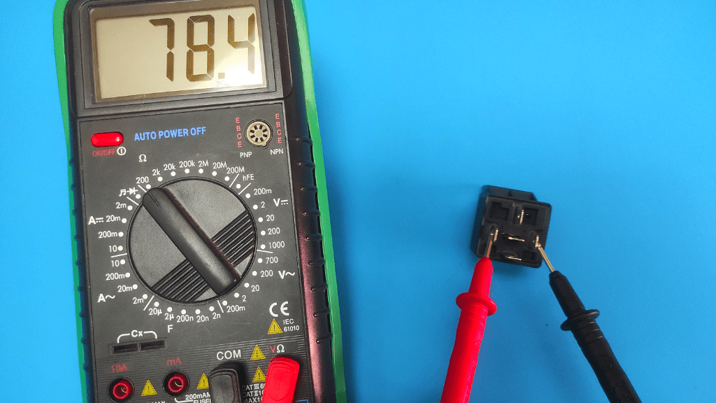
Put the multimeter in the Ohms setting to measure resistance and place your probes on the two normally open switch pins typically labeled ”85” and ”86”. An “O.L” reading or any value from the meter that is not between 50Ω and 200Ω means the relay may be faulty.
You may also perform a clicking test on the relay, and all these will be explained as we move further.
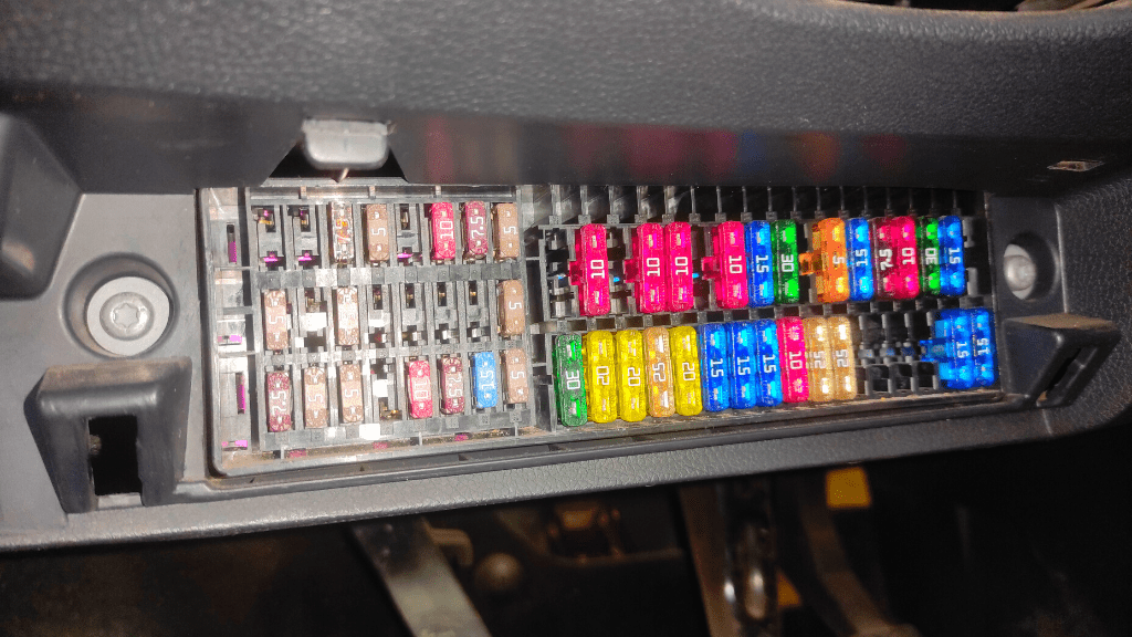
- Locate The Relay
The first step to running a test on a relay is to get your hands on it. Typically, relays in cars are located in the fuse box, but you may refer to your car manual to know exactly where it is within your vehicle. Once you find the relay, gently take it out of its slot.
You may proceed to wipe the pins with a clean cloth to rid them of any contamination, as this is one of the causes of a malfunctioning relay. If it still doesn’t work, move to the next test step.
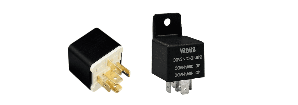
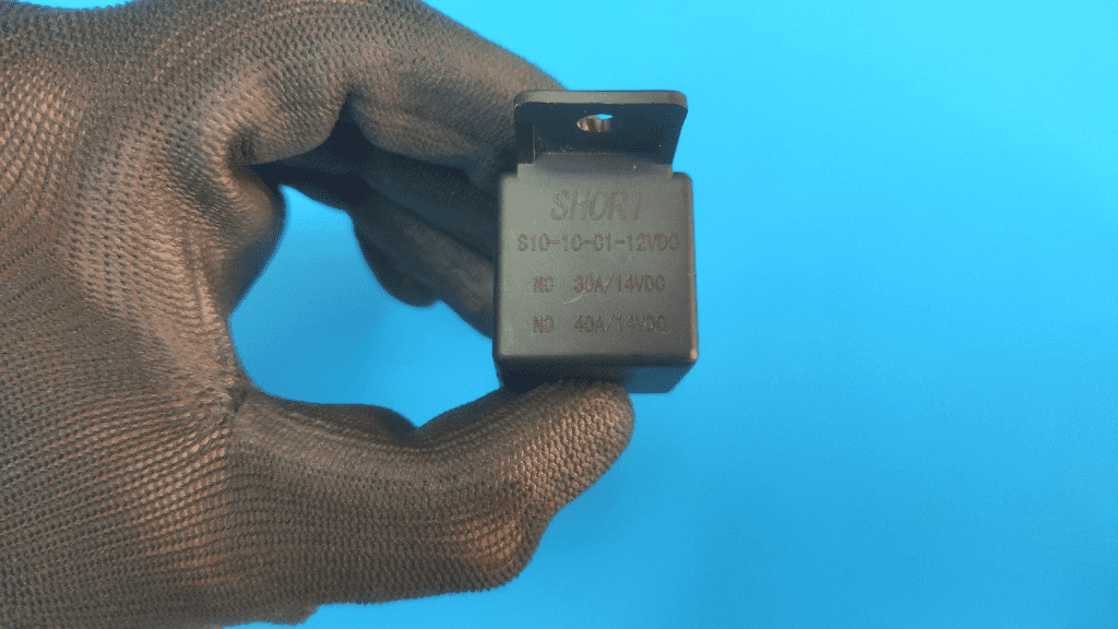
- Check The Type Of Relay It Is
Here, you identify whether your relay is diode-protected or not, and also find out the voltage rating, which could either be 5V or 12V. This is important as the presence of a diode determines if we consider the polarity of our subsequent connections or not. You also don’t want to damage the relay by running excess power through it.
Look towards the internet for information on your specific relay model (search on the model number for easy results).
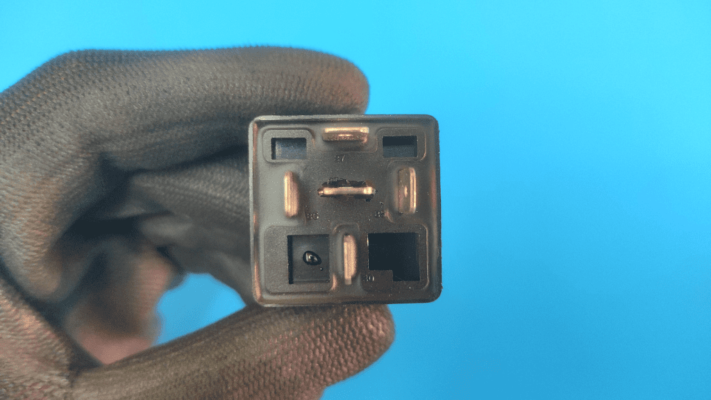
- Identify The Normally Closed Pins
Relays come in different forms, and the more common are the 4-pin relays and the 5-pin relays. Now, in a 4-pin relay, the normally closed (NC) pins are usually identical pins labeled “85” and “86” while the normally open (NO) pins are labeled “87” and “30”. 5-pin relays come with an additional COM pin usually labeled “87a”.
If all your pins look alike, these labels help you to identify each of them. In case your relay doesn’t come with these labels, the NC pins are typically opposite or diagonal to each other. Checking the internet for a guide on your specific relay model is the best.
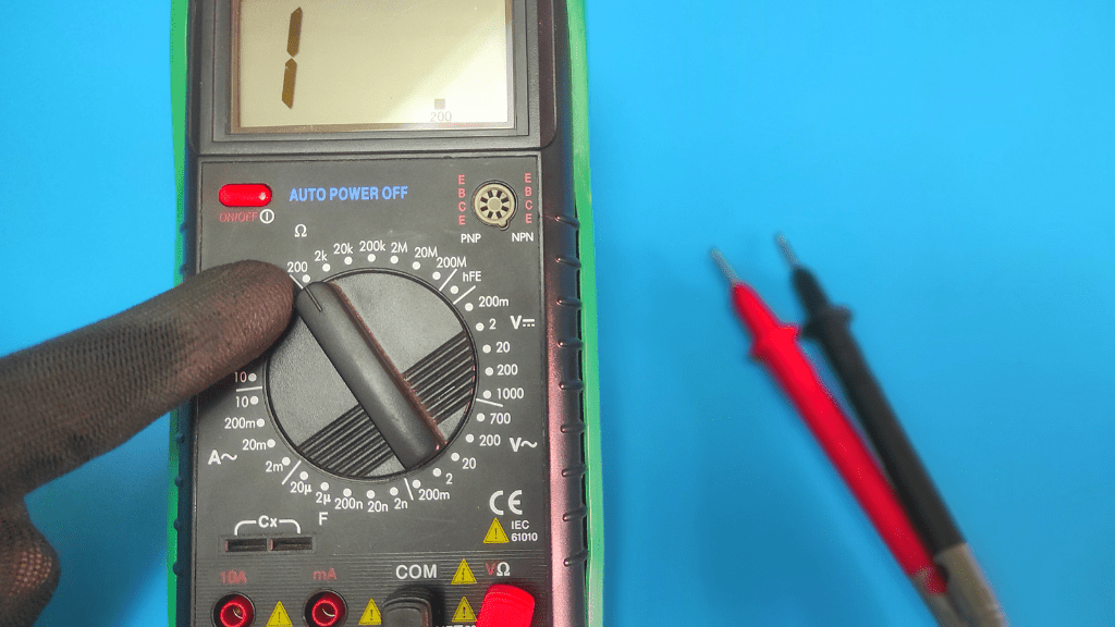
- Put Multimeter In Ohms Setting
To see if your relay is in good condition with a multimeter, we test the continuity and resistance between the two normally closed pins and the two normally open pins.
Set the meter to measure resistance by putting it in the Ohms setting. While the Ohms setting is usually represented by the Omega symbol (Ω) on the meter, you also want to set the dial to the 200Ω range to get accurate results.
- Connect Probes To The Relay Normally Closed Pins
As mentioned before, the NC pins are typically identical and labeled “85” and “86”. You firmly connect your meter probes to both of them, more preferably using alligator clips. The polarity of the leads does not matter in this resistance test.
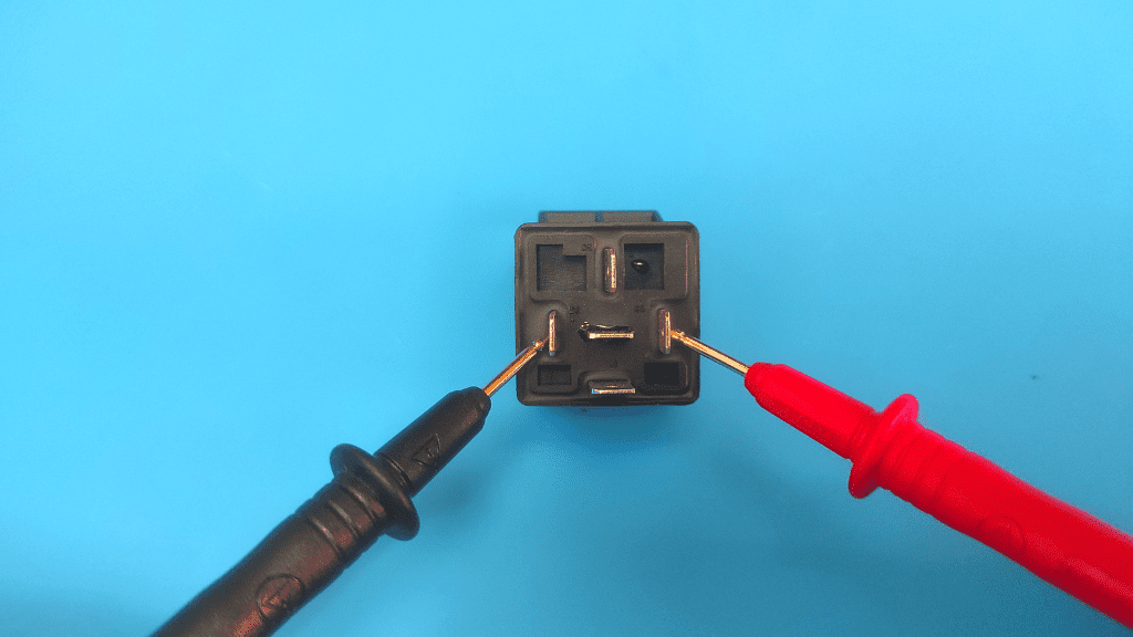
- Check For Control Circuit Resistance Between 50Ω and 200Ω
If the relay coil is in good condition, the meter presents a resistance reading between 50Ω and 200Ω depending on the model the relay is. If you get a value outside this range, then your coil may be bad and the entire relay may not be working.
Additionally, if you get “O.L” from the multimeter, then there is a broken circuit within the relay, which is most expected to be a break in its coil. You should replace the relay at this point as it may not be working.
However, if you got a reading indicating the connection between NC pins is good, then you may test the connection between the NO pins. You will need a 12-voltage battery and jumper cables for this.
- Place Probes On Relay Normally Open Pins When Coil Is De-energized
First up, you test the connection before energizing the relay (while the contact is still open). Connect the multimeter probes to the pins labeled “30” and “87”.The circuit is expected to be open at this point and the meter presents you with “O.L”, indicating an open loop.
If you get any resistance reading when you check the meter, then there is a short within the relay and it should be replaced.
For 5-pin relays, before energizing, you may check the connection between the NO pin labeled “30” and the COM pin labeled “87a”. You should get a resistance reading close to zero (0). An “O.L” reading here indicates there is a problem with the relay.
If you didn’t find any issue in these tests, wear an insulated rubber glove and then proceed to the next test step.
- Energize The Relay Coil
Now, we close the path between the load terminals by supplying power to the relay coil and acting on the contact.
If you use a 12V relay, connect the ends of the jumper cables to the positive and negative posts of a 12-voltage battery and connect the other ends to the NC pins. For 5V relays, look for an appropriate power source.
If you use a diode-protected relay, polarity matters when making these connections. You connect the positive jumper cable to the NC pin labeled “85” and connect the negative jumper cable to the NC pin labeled “86”.
You should probably hear a click at this point. If you didn’t hear a clicking sound, then the coil is bad or the relay is most likely not working. This isn’t an entirely reliable conclusion though, so the multimeter test helps you clarify.
- Place Probes On Normally Open Pins When Energized
Place the multimeter probes on the NO pins with firm contact and check the meter for a resistance value.
- Check For Load Circuit Resistance Between 0.2Ω and 0.5Ω
When the coil is energized with power, the resistance between the NO pins is expected to be very low. If the relay is good, you see values between 0.2Ω and 0.5Ω. A value above this range or the meter presenting you with “O.L” indicates that the relay isn’t working and you should replace it.
VideO gUIDE
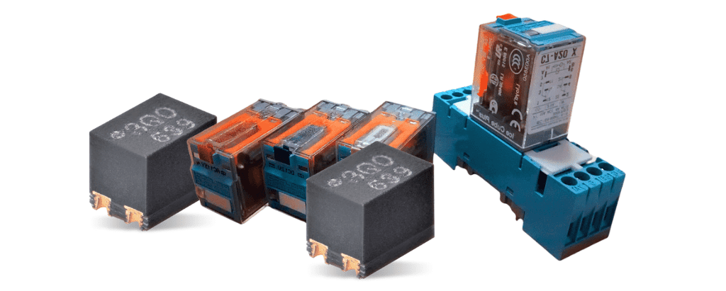
Other Types OF Relays You May Come Across
An alternative to the electromechanical switch is a solid-state relay, which abandons the use of mechanical moving parts and opts for semiconductors to facilitate circuit switches.
Other types include coaxial relays, heavy-duty contactors, mercury relays, latching relays, and polarized relays, among a barrage of others. How you test these may differ from how you test a car’s electromechanical relay.
Conclusion
Simply replacing an old relay with a new one seems to be the easiest way to know if the former is working or not.
However, you risk damaging the new relay if the old relay was spoilt by another electrical fault in your vehicle. This is why running a separate and accurate test on the relay with a multimeter is your best option. A multimeter is a great tool to also test other components in your vehicle and home.
FAQ
What Are The Common Faults Of Relays?
Relays stop functioning well due to an incomplete circuit caused by an electrical short, mechanical fault, or contamination by dirt. A simple wipe or multimeter test helps you diagnose the problem.
What Happens When A Relay Goes Bad?
A bad relay leads to a stalling engine, draining battery, or flicking dashboard lights. At worst, you don’t get a power supply to your entire ignition system or the component the relay is dedicated to.

Author
Alex Klein is an electrical engineer with more than 15 years of expertise. He is the host of the Electro University YouTube channel, which has thousands of subscribers.