
How To Identify Line And Load Wires
Whether you’re a DIY enthusiast or just want to know how line and load wires work, differentiating between them can be a little hectic. In our article, we will tell you what the line and load wires do, as well as how to identify or differentiate between them when working on switches or an outlet in your home.
Let’s get right in.
What Are Line And Load Wires
The line and load wires are important components of any electrical system in your home, as they are key to the flow of current along the circuit.
The line wire carries power from the main power source and supplies it to a terminal such as a switch or GFCI outlet. It is always life with current, as long as there is supply from the main power source.
It is only hot when the receptacle switch is turned on (signaling a closed circuit that allows current to flow through).
The load wire, on the other hand, takes current out of the terminal and supplies it to electrical devices or other terminals along the circuit. The load wire does not carry power out unless the terminal or receptacle permits it.
For instance, the line wire is the one that supplies power from your home’s circuit panel box to a light switch. The load wire, on the other hand, goes from the light switch to the light bulb. It only carries current when the switch is turned on, helping to regulate the power supply to the bulb.
There is usually a third wire, an idle ground connection that specifically works with the line wire and protects against fatal electric shocks.
A bad connection of the line and load in a GFCI socket wiring in your house, for example, makes its circuit breaker useless and presents you with a fatal shock hazard.
This is why you need to identify the wires before making any connections.
Tools Required To Identify Line And Load Wires
The tools required to identify your line and load wires include
These help to provide more accurate results.
How To Identify Line And Load Wires
The line is usually a black insulated wire that goes to the bottom of the switch while the load is a red wire that goes to the top of the switch. Alternatively, you may use a voltage tester or multimeter to check for a voltage reading from one of the wires.
There is more to these identification methods as well as other ways you may identify the line and load wires. We will get into them now.
Identifying Line And Load Wires Through Color
The easiest way to distinguish between your line and load wires is through color codes.
Generally, wires are insulated with rubber to safeguard us from electrical shock hazards. These rubber insulators also come in a barrage of colors and have a specific meaning.
Regarding line and load wires, black rubber is typically used for the line while red rubber is used for the load. If you have your wires in this color code, your problem is solved.
However, there’s still an issue. Since the color of the wire doesn’t have anything to do with whether they work or not, color codes may be interchanged.
For instance, the red rubber may be used for the line instead of the load and vice versa.
Sometimes, the line and load wires may be the same color. This is where other methods of identification come in.
Identifying Line And Load Wires Using Position
The line and load wires are peculiar to wall outlets and switches and have different positioning due to their functions within these receptacles.
The line is usually positioned at the bottom of the switch as it supplies power, while the load is usually positioned at the top.
This is another easy way of differentiating between these two wires. Nonetheless, there may still be confusion. You may be unable to identify which part of the switch is the top and which part is the bottom.
Additionally, as many people may find themselves, what if the wires are idle and not even connected to a switch in the first place? How, then, do you accurately identify them?
Identifying Line And Neutral Wires Using A Non contact Voltage Tester
One of the most unfailing methods of identifying your line and load wires is with the use of a non contact voltage tester.
A non contact voltage tester is a device that gives off a beep or illuminates a light when its tip comes close to electricity or voltage. This is regardless of whether or not the copper wires carrying the electricity are exposed.
Now, only one carries current when the line and load wires are idle or disconnected from the switch, or when the switch is turned off. This is the line wire.
You simply use the tip of your voltage tester to touch the insulation of each of the wires to be identified. The wire that gives off a beep or light is your line wire, and the other wire is your load wire.
Using a voltage tester is a safer method than using a multimeter to identify your wires. Nonetheless, the multimeter is more readily available to everyone as it serves a variety of purposes.
Identifying Line And Load Wires Using A Multimeter
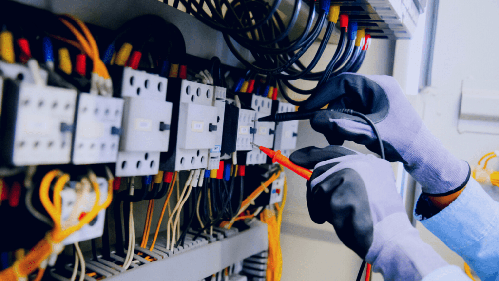
With the multimeter, you have to make contact with exposed wires, so you want to be careful here. Make sure you wear insulated rubber gloves to avoid shock hazards.
Plug your black negative multimeter probe into the “COM” port and plug your red positive probe into the “VΩmA” port.
Proceed to turn the multimeter dial to the 200 AC voltage range represented by “VAC” or “V~” on the multimeter.
Now, place the black lead on any metal surface and the red lead on an exposed part of your wires. You may have to disconnect them to see these exposed parts if they are connected to a switch.
Alternatively, you may also place your probes on the screws that hold the wires in place on the switch or meter box.
Once you do all these, the multimeter is expected to present a 120 volt reading on one of the wires. The wire you get this reading from is your line, while the other wire that doesn’t give any reading is your load wire.
Like the volt tester, the multimeter also gives you as accurate as possible results. There are no changes that may be made to this.
Identifying Line And Load Wire Using A Neon Screwdriver
A neon screwdriver is a tool that works just like the volt tester but requires contact with exposed wires. A screwdriver gives off a common red light when in contact with electricity.
Place the tip of your neon screwdriver on the exposed parts of your wires or on the screws that hold them in place on the switch or meter box.
The wire that makes the neon screwdriver illuminate is your line wire; the other is your load wire.
Remember that when carrying out procedures with your volt tester, multimeter, or neon screwdriver, the switch is expected to be turned off. This cuts off the power supply within the circuit (or between line and load).
Conclusion
There are multiple methods of differentiating between the line and load wires in a switch.
Using color codes and positioning is easier but isn’t entirely reliable, while the multimeter, volt tester, and neon screwdriver tests are more dependable.
Frequently Asked Questions
How Do You Identify The Line And Load Wires Of A GFCI?
In a GFCI socket, you use a non contact voltage tester, multimeter, or neon screwdriver to check for voltage from the wires. The wire that has voltage is your line wire and the other is your load wire.
What Happens If I Reverse Line And Load?
The outlet and electrical appliance still work but hold a potentially fatal shock hazard. This is because the circuit breaker is disabled and the live line wire isn’t connected to ground anymore.

Author
Alex Klein is an electrical engineer with more than 15 years of expertise. He is the host of the Electro University YouTube channel, which has thousands of subscribers.